
Description
This module is designed to work as the pointing program in an ADCS software chain as shown in the figure below.
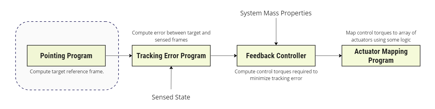
This model provides a general method to establish a pointing frame between two known positions. Specifically, this module constructs a reference frame that aligns a vector () defined by the user in the body frame of the parent object with a vector that points to a target object () in the body frame. This is for one Spacecraft to point towards another.
Example Use Cases
- Space-based Observations: Establish a pointing reference frame between a nearby space object and an on-board sensor.
- Terrestrial Observations: Establish a pointing reference frame between a plane based on received ADS-B (flight tracking) position information.
Module Implementation
The relative pointing frame is constructed about a principal pointing axis, which is derived from the inertial position of the parent spacecraft and target :
A coordinate system about this principal axis is then built such that:
Where and the DCM is . The angular velocity of the frame may then simply be calculated from the time-step as:
Using this result, and applying equation 3.164 in [1], the angular velocity of the frame with respect to in the frame components may be computed as:
The above definitions will align the reference frame’s x-axis with the target. To align with a user-specific vector, we create a second coordinate frame . In the case that the frame aligns with the frame, has to align with . For this reason, an frame is built around the vector, such that:
where all the above are in . The resultant DCM . Converting to MRPs, the final rotation between and is simply:
The angular velocity and angular acceleration remain the same.
Parameters
| Parameter | Units | Description | Default |
|---|---|---|---|
AlignmentVector_B | — | Body-frame vector defining the axis to align with the target | (Up) |
Assumptions/Limitations
- The first two simulation steps produce zeroed angular velocity and angular acceleration outputs due to the numerical differentiation method used.
- If
AlignmentVector_Bis set to zero, it defaults to the body +Z axis. - The module assumes the input navigation messages provide valid inertial position data for both the parent spacecraft and target.
- MRP shadow switching is handled automatically to avoid singularities when the rotation approaches .
References
[1] Hanspeter Schaub and John L. Junkins. Analytical Mechanics of Space Systems. AIAA Education Series, Reston, VA, 3rd edition, 2014.