Description
This module is designed to be used as the tracking error module in an ADCS software chain as seen in the figure below.
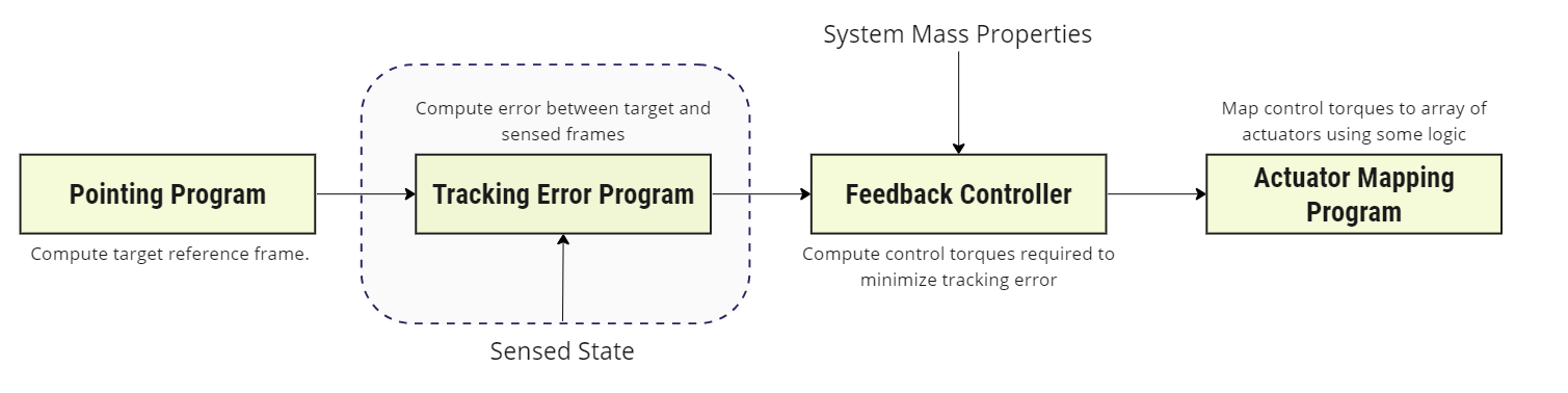
That is, given an input target reference frame and estimated (or actual) body frame , this module outputs the guidance frame that drives to a corrected body-frame that aligns with .
Example Use Cases
- Compute the error between the desired frame and the sensed state: Given some desired attitude reference state, this module computes the error relative to the sensed state. This sensed state may be the body’s actual state or an estimated state determined by sensors.
Module Implementation
Reference Frame Definition
Given a body-fixed frame , corrected body frame and uncorrected reference orientation , the goal of this module is to compute the attitude guidance message that drives i.e.
Where is the inertial frame. Re-arranging for the inertial body frame gives:
The corrected reference frame is, therefore:
where the body-frame correction is subtracted from the original reference orientation to give the error between the current and target frames.
Reference Frame Angular Velocity Vector
The angular velocity of the original reference frame is . The angular velocity tracking error may then be defined as:
Because the body frame correction is a constant angular offset (), the reference frame angular velocity is:
The required inertial reference frame rate vector, in the body frame, is given by:
Reference Frame Angular Acceleration Vector
may be expressed in the body frame as:
Angular Velocity Tracking Error
The angular velocity tracking error in is then written as:
References
[1] Hanspeter Schaub and John L. Junkins. Analytical Mechanics of Space Systems. AIAA Education Series, Reston, VA, 3rd edition, 2014.