Description
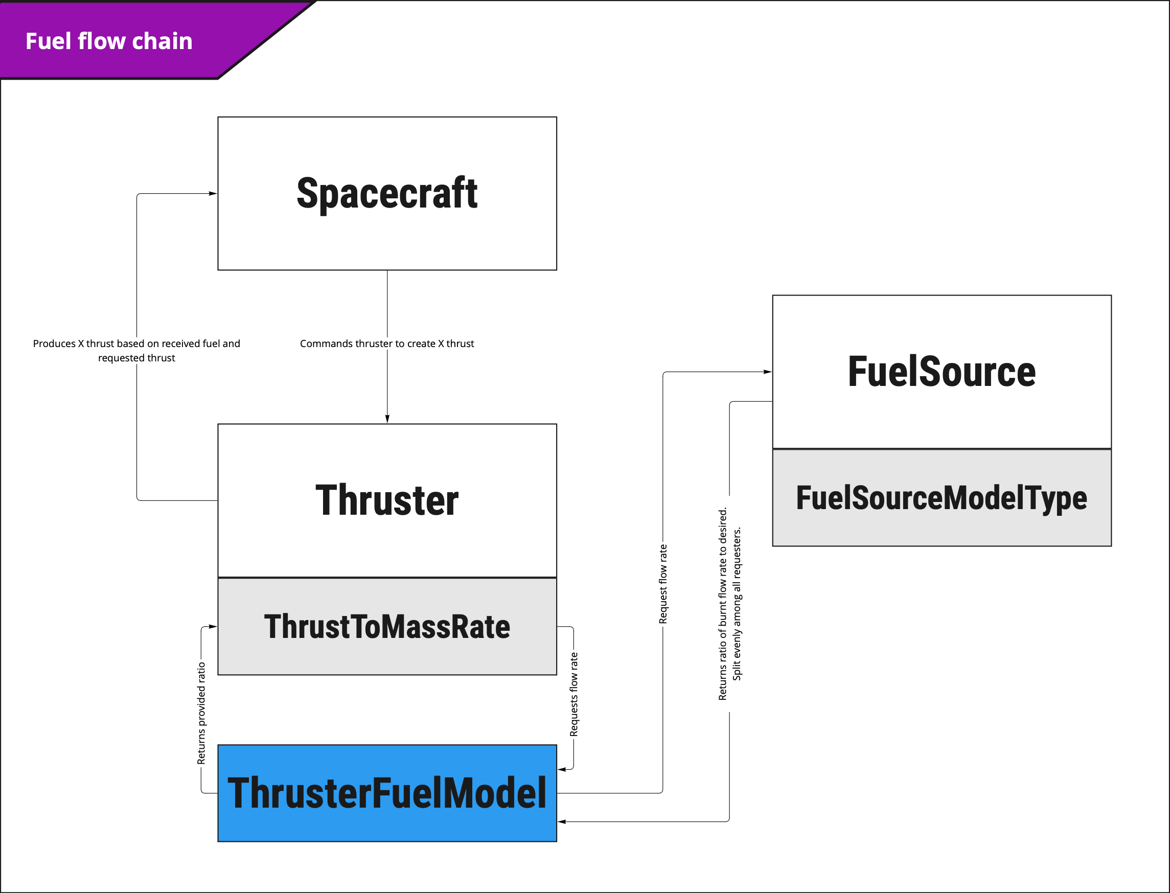
The fuel source is designed to contain fuel and act as a source of fuel for Fuel Consumers such as thrusters that consume mass during use. Fuel consumers will automatically link to the first fuel source they can find on the spacecraft. If they are unable to find one they will assume they have the full desired fuel flow. Before the update is called on the spacecraft, the fuel source will calculate how much fuel is requested from the attached fuel nodes and provide a ratio of how much fuel can be returned to them. The fuel flow provided is split evenly amongst the fuel nodes. The Fuel Source can also be configured to use different consumption model types.
Example Use Cases
- Model fuel consumption in the spacecraft A fuel source can be used in conjunction with a fuel consumer such as a thruster to simulate thrusters using mass and the mass properties affected by its use**.**
- Model Moment of Inertia of Fuel Source The fuel source will also calculate its moment of inertia in real time and is applied to the component.
Module Implementation
Nomenclature
| Parameter | Description |
|---|---|
| The length of the cylindrical tank | |
| The mass moment of inertia about the centre of mass of the propellant tank in the local tank coordinate frame. | |
| The first principal moment of inertia of the propellant tank in the local tank coordinate frame. | |
| The second principal moment of inertia of the propellant tank in the local tank coordinate frame. | |
| The third principal moment of inertia of the propellant tank in the local tank coordinate frame. | |
| The time rate of change in the first principal moment of inertia of the propellant tank in the local tank coordinate frame. | |
| The time rate of change in the second principal moment of inertia of the propellant tank in the local tank coordinate frame. | |
| The time rate of change in the third principal moment of inertia of the propellant tank in the local tank coordinate frame. | |
| The mass of the propellant tank at an instance of time. | |
| The time rate of change in mass of the propellant tank | |
| The mass density of the propellant | |
| The radius of the propellant tank | |
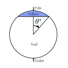
| The angle about the centre of the tank, from the pole to a point on the circumference defines the border of the base of the spherical cap. |
Fuel Sources
Five different fuel source models are provided to allow users to best match the properties of their desired fuel chain configuration. Each model for the geometry of tank depletion has a unique formula for determining the instantaneous mass moment of inertia (MoI) and time rate of change in MoI about the tank frame. These parameters are used to account for the shift in mass distribution within the tank on the translational and rotational dynamics of the spacecraft. These are described in the following sections for each fuel source type.
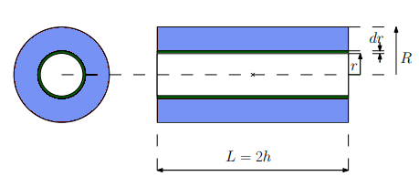
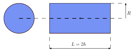
Centrifugal Burn Fuel Source
The centrifugal tank model features a cylindrically shaped tank where the propellant burn pattern depletes radially out along the entire central axis of the tank to the outer shell.
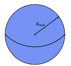
Constant Density Fuel Source
Features a spherical tank with a radius that changes to maintain the density of the fuel. Due to the symmetry of the homogenous fuel density distribution about the sphere, the centre of mass of the fuel remains fixed.
Constant Volume Fuel Source
In this model, a spherical tank maintains its volume. This entails that the tank’s radius is constant and results in the barycenter of the tank being fixed at the centre of the tank.
In this case, the mass moment of inertia and its time rate of change are given by:
Emptying Fuel Source
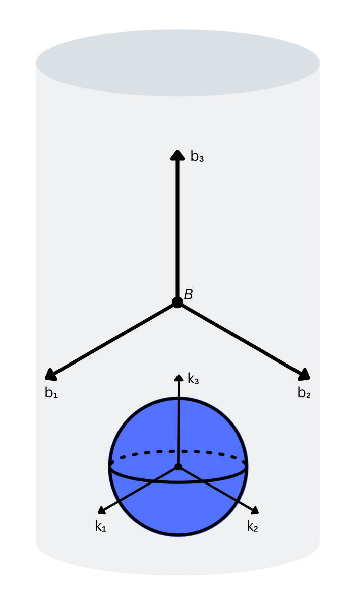
Here, a spherical fuel tank is modelled featuring an outlet at a single point on the sphere. The tank begins to empty from a point on the polar opposite side from the outlet which will now be called the pole. The fuel depletes to leave a spherical cap-shaped hollow with the point of the spherical cap hollow corresponding to the pole. The spherical cap hollow is symmetric about the outlet-to-pole axis and grows in size as more fuel is depleted.
In the following formulation of the moment of inertia of the fuel tank, defines the angle about the centre of the tank, from the pole to a point on the circumference defining the border of the base of the spherical cap.
The values for the mass moments of inertia are presented in their final form as derived by Panicucci et. al. [2].
Uniform Burn Fuel Source
This features a cylindrical tank of constant geometrical shape where the volume of propellant remains fixed and the density of the propellant changes as propellant is depleted.
Assumptions/Limitations
- Fuel consumers can only attach to one fuel source.
- There is no relative rotational motion between the rigid body hub and the propellant in the tank.
- There is no thrust vectoring. It is assumed that the thrusters are fixed relative to the hub and that the thrust vector is aligned with the thruster axis.
- There is no swirl within the thruster plume. That is, there is no rotational relative motion between the ejected propellant and the rigid body hub.
- The dynamic effect of the movement of the mass as the propellant moves between tanks and thrusters is not taken into account.
- This module does not consider the dynamic effects of fuel slosh, rather it is delegated to an independent module.
- The mass and mass moment of inertia of the propellant tank are not added to the rigid body mass when setting up a simulation. The propellant mass and moment of inertial properties are added to the spacecraft dynamically during the simulation.
- Products of inertia (e.g. ) are zero/negligible as symmetry in at least one axis is assumed.
References
- Paolo Panicucci, Cody Allard, and Hanspeter Schaub. Spacecraft dynamics employing a general multi-tank and multi-thruster mass depletion formulation. In AAS Guidance, Navigation and Control Conference, Breckenridge, CO, Feb. 2–8 2017. Paper AAS 17-011.