Description
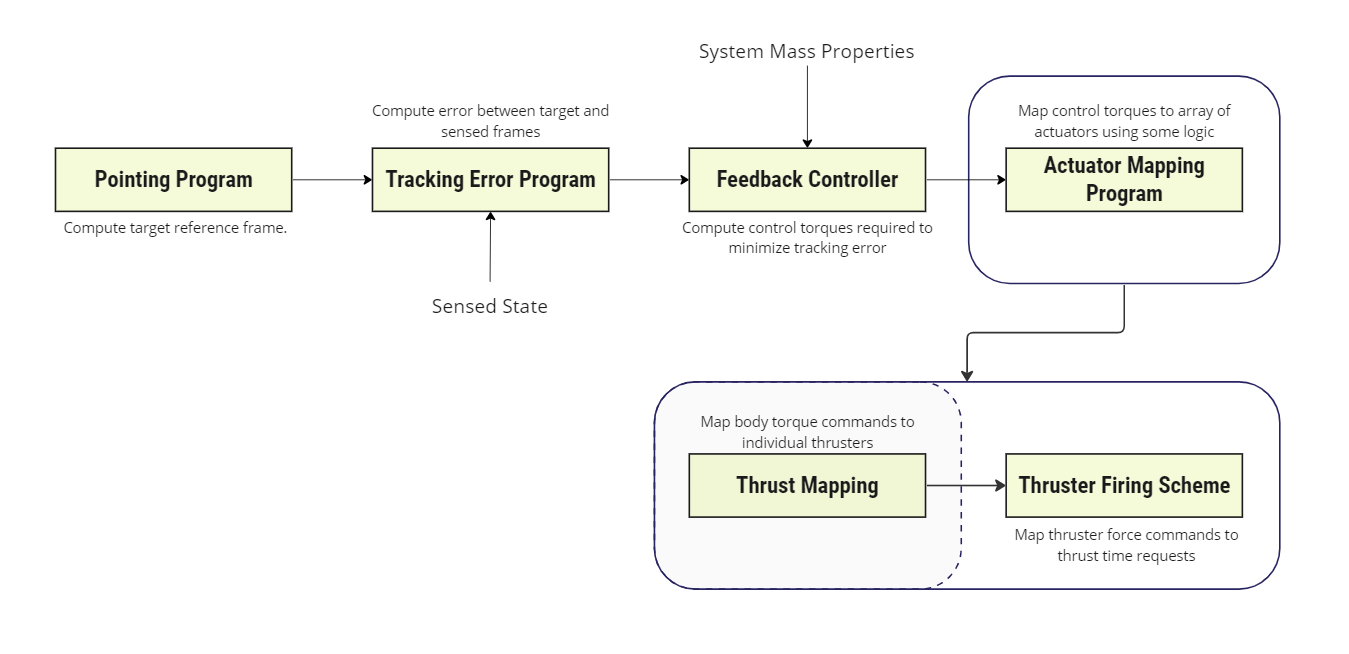
This module is designed to be used as part of an actuator mapping program, as illustrated below. The purpose of the thrust mapping module is to provide a general algorithm that maps a desired external body frame control torque () onto a cluster of Thrusters such that the set of thruster force commands that yields .
 Two types of thruster configurations are supported:
- RCS Mode: This mode assumes that the configured cluster of thrusters can produce pure torque-couples without exerting a net onto the spacecraft. The thruster force values must be strictly non-negative. Note that this means that the case is a null space (no net force or torque).
- DV Mode: This mode assumes that the cluster of thrusters’ force axes are all aligned i.e. no control along the thrust axis. To provide torques orthogonal to the thrust axis assumes the thrusters are capable of off-pulsing. This means that the thrust mapping allows for negative values.
Example Use Cases
- RCS Thruster Mapping: Compute the firing solution for an RCS thruster configuration.
- DV Thruster Mapping: Compute the firing solution for a DV thruster configuration.
Module Implementation
The general goal of this model is to compute the solution to such that , where is the thrust mapping matrix. The following sections:
- Describe the general definition of the mapping matrix
- The solution strategy for for an RCS thruster configuration, with both complete and partial control authority.
- The solution strategy for for a DV thruster configuration, with both complete and partial control authority.
Mapping Matrix
The torque vector produced by the thruster about the body’s total centre of mass () can be written as:
Where is the position of the thruster in the body frame and is its unit thrust pointing vector and is the thruster magnitude. Summing across thrusters, the total torque on the system is then,
Expressed in matrix form, the net torque on the spacecraft can be written as,
RCS Thrust Solution
With Complete Control Authority
Here the thruster configuration is assumed to be able to produce pure torque couples without exerting a net force on the spacecraft. The thruster magnitudes must be strictly non-negative.
The first step is the perform a standard minimum norm inverse solution to solve for such that,
This solution will include both positive and negative values.
To achieve a solution where all values of are strictly non-negative, the minimum is identified and subtracted from for N force values i.e.
This is only possible due to the assumption of pure force couples, as it transfers the negative components of the force couple to their positive counterparts.
With Partial Control Authority
There may exist use cases where the user specifies a control frame that results in reduced degrees of freedom e.g. only 1 or 2 control axes are explicitly specified). In this case, the mapping matrix and control torque must be projects into i.e.
As in the above case, we then apply the minimum norm inverse to solve for ,
However, care must be taken as is not invertible if one or more control axes are a zero vector. To address this problem, is initialized as an identity matrix and then only the upper block entries in are computed. For example, for a two-axis control scheme,
While the uncontrolled element in is zeroed, such that the 1 in the above case will have no effect on the solution.
DV Thruster Solution
Unlike the RCS assumption, the DV thruster configuration assumes that multiple thrusters are aligned in a common direction () and that the default status of the thrusters is on and that the configuration is such that there is no net torque on the body when all thrusters are firing (thruster are still in torque pairs).
NOTE
This also means that it is expected that the solution to will also apply a net thrust on the body.
As a result, thrusters are able to produce negative solutions through off-pulsing i.e. turning the thruster off will result in a negative torque compared to it’s default state.
A similar procedure is followed as in the RCS solution, the first step is to find the minimum normal solution to using the partially controlled solution as the DV configuration by definition will not be able to apply torques about the DV-axis.
NOTE
The user must specify this, the algorithm does not check for it.
The solution, as in the RCS solution, will correspond to the following,
Unlike in the RCS case, negative values will not be removed. However, to improve robustness, we can apply a second-stage minimum norm solution, where we evaluate the initial solution to for thrusters that are not firing. For example, for a 6 thruster configuration where thruster 2 and 4 are not firing would result in the following,
A new solution can then be re-computed using the subset of thrusters that are firing using the same procedure as in the RCS case, without the subtraction of minimum negative components. The resulting solution should remain a valid solution.
This 2nd stage solution can also be used in the RCS configuration and allows for the case where a subset of thrusters are unavailable (e.g. offline).
NOTE
While thrusters may be specified as offline, the configuration requirements of the solution must be maintained otherwise the mapping solution may be invalid e.g. if one thruster in a torque pair is taken offline, its pair must also be taken offline.
References
[1] Hanspeter Schaub and John L. Junkins. Analytical Mechanics of Space Systems. AIAA Education Series, Reston, VA, 3rd edition, 2014.