This guide will build a simulation to have Synchronous External Hardware Integration. This approach to External integration can be useful when the Simulation and External Device depend on each other. However, the simulation rate will be reduced due to the codependent link. Zendir Editor could also become unresponsive if care isn’t taken to account for Unreal’s single-threaded nature. It is assumed that the “Integrating External Hardware or Software” guide has been read beforehand and users have at least an Intermediate knowledge of using Zendir Editor.
WARNING
The functionality for external hardware depends on a valid hardware connection to the device running Zendir Editor and, depending on the use, a valid port that can be opened. As such, the functionality of this feature may depend on the environment in which Zendir Editor is being run. Cloud deployments, for example, may not run hardware functions.
This guide will use the provided Demo_USB stimulation level as a practical example of Synchronized External Integration. In this Demo, an EPS focused simulation is performed, with the Power and Voltage Data of multiple solar panels exported from the simulation over USB. The exported data is used to control a series of Power Supplies that are connected to a benchtop Battery Management System (BMS) and battery. The simulation then receives an updated battery state to compare to it’s digital twin. For the purposes of the Demo, the Power Supplies, Battery and BMS are all emulated on an Arduino Microcontroller.
Connection Initialization
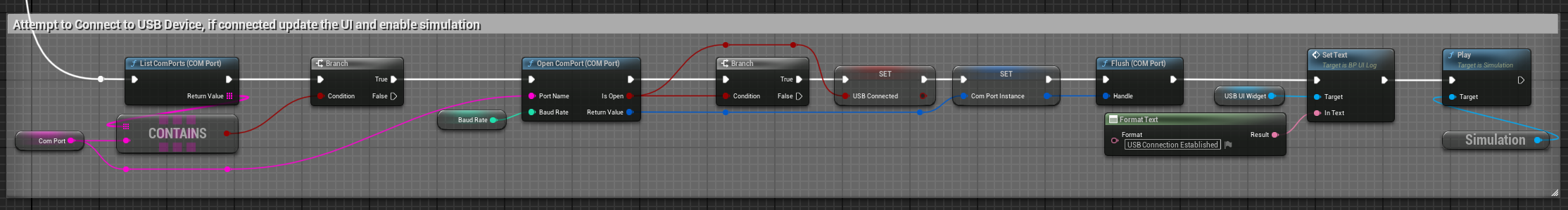
During the Begin PlayEvent, a connection to the Arduino Microcontroller is configured. Specifics of which are available in the “USB External Integration” Operator Guide. The connection is then opened on the Event Tick Event, as the simulation is Paused at the end of Begin Play. Once the USB Connection has been established, the simulation ticks once per received packet. For each iteration of the Event Tick Event, the simulation checks if the configured COM Port is detected and attempts to connect, if the connection is successful the UI is updated and the simulation is enabled.
Data Flow
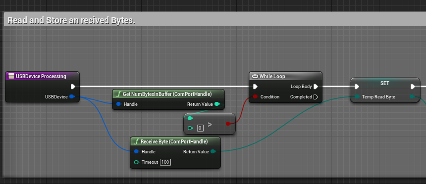
To prevent the Zendir Editor from becoming unresponsive whilst communicating with synchronous external devices, the flow of data needs to be structured to occur over multiple rendered frames. Therefore, it is advised to use reasonable Timeout values in receiving values and to restrict the use of Loops. In the below example, a timeout of 100 milliseconds is used in a while loop that only runs when there is data to be read in from the Serial buffer. This prevents the example USB Device Processing function from hanging for a complete packet and locking the rendered frames.
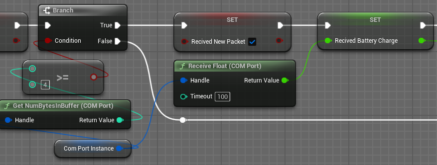
Alternatively, if a number of bytes to the received packet is known, the logic can be updated to only read in from the COM Port Buffer when there are at least that many bytes. As shown below, the Demo_USB is expecting a float which is 4 bytes.
Simulation Tick
In the referenced demo, the external hardware device only sends back a single packet type. Therefore, whenever a new packet is received, the Zendir Editor needs to complete any updates based on the received data and tick the simulation. As this is a synchronized hardware integration simulation, Zendir Editor only executes a single step instead of the several per visualized frame of the other provided demos.
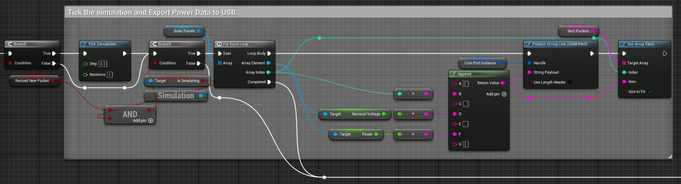
If the packets are received from multiple devices or multiple packet types can be received, additional logic is required to determine when to tick the simulation. The simulation step could occur once a packet has been received from every connected device OR only when a Tick Simulation packet has been received.