Adjusting the Sink
For this tutorial, when the camera takes an image, the camera should take some power from the battery. In a previous document, the Power Sink was configured in the power network to be the load that uses battery power. This can be done by adjusting the power of the sink. Using the formula
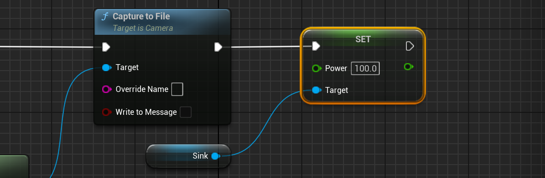
where is the power, is the voltage and is the resistance of the node, given that the voltage is constant, the lower the resistance, the more power is used by the component. As such, changing the power of the load to something small (but non-zero), will increase the resistance internally in the network. Once the image is taken, the power draw of the sink should be increased. This is done on the Capture function created in the previous tutorial.
NOTE
The actual power that is drawn from the sink is dependent on the circuit design. Drawing a 100 watts will not result in an actual drawing of this power as it is limited to the current and voltage of the network.
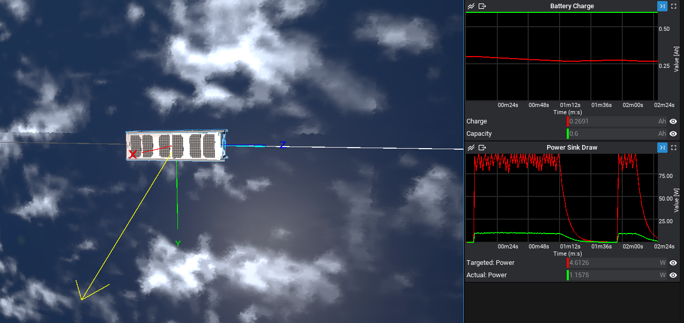
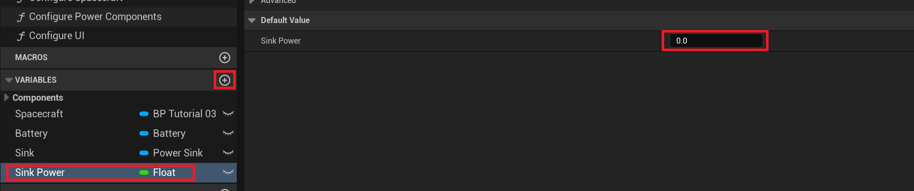
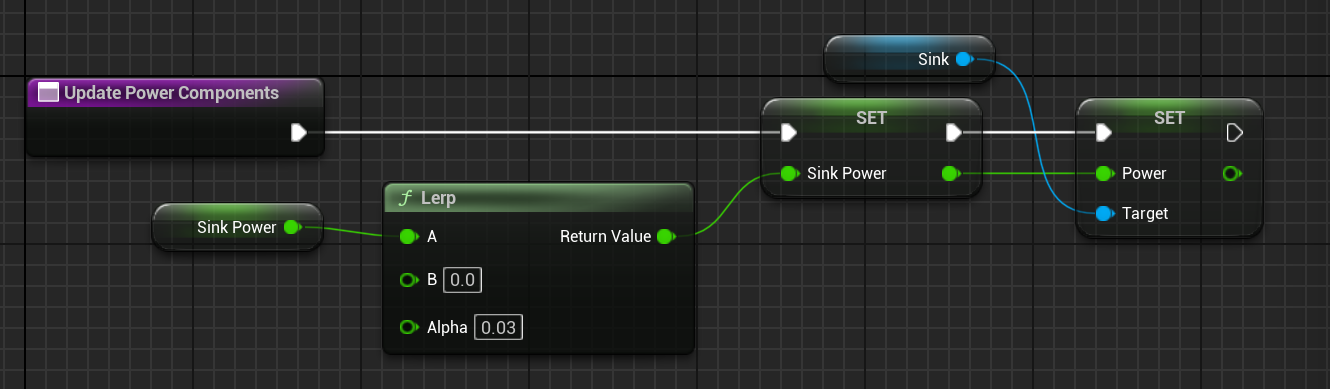
When the simulation is played and the image is taken, the battery starts to drain. However, it does not stop and will continue to drain until no charge is left in the battery. This is not ideal for this simulation as it would assume that the camera is constantly drawing power. A better approach to this is to use a linear interpolation between some value and 0 and update that value when the camera is used. By having a low power, very little current will be drawn from the camera sink. The power can then be updated to the interpolated value. Start by creating a new float variable, named Sink Power, and setting the default to 0 watts.
NOTE
If the default value does not appear, make sure to compile the demo Blueprint first.
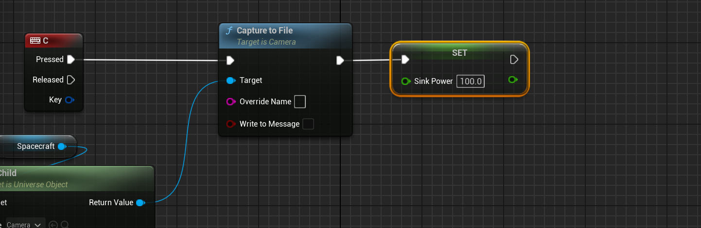
When the Camera takes the image, that variable should be set to 100 watts or some appropriately large value. Drag the property from the variables tab and select Set Sink Power. Make sure to remove the previous code for the power sink.
Then, on the Tick event, a new function called Update Power Nodes can be created and added. Within this function, the power should be updated so that it uses a linear interpolation between the current value and 0. Typically, functions like this should occur before updating the user interface, as the UI should be the last step in each event. The alpha value defines the interpolation value, which can be hard coded. From there, the resistance of the sink itself can be set to the value from this variable.
Capture Logic
Returning to the Capture Image function, some logic needs to be implemented so that the camera can only take a photo if the charge of the battery is greater than 45%. This can be done by checking the Charge Fraction of the battery is greater than 0.45 using a branch node.
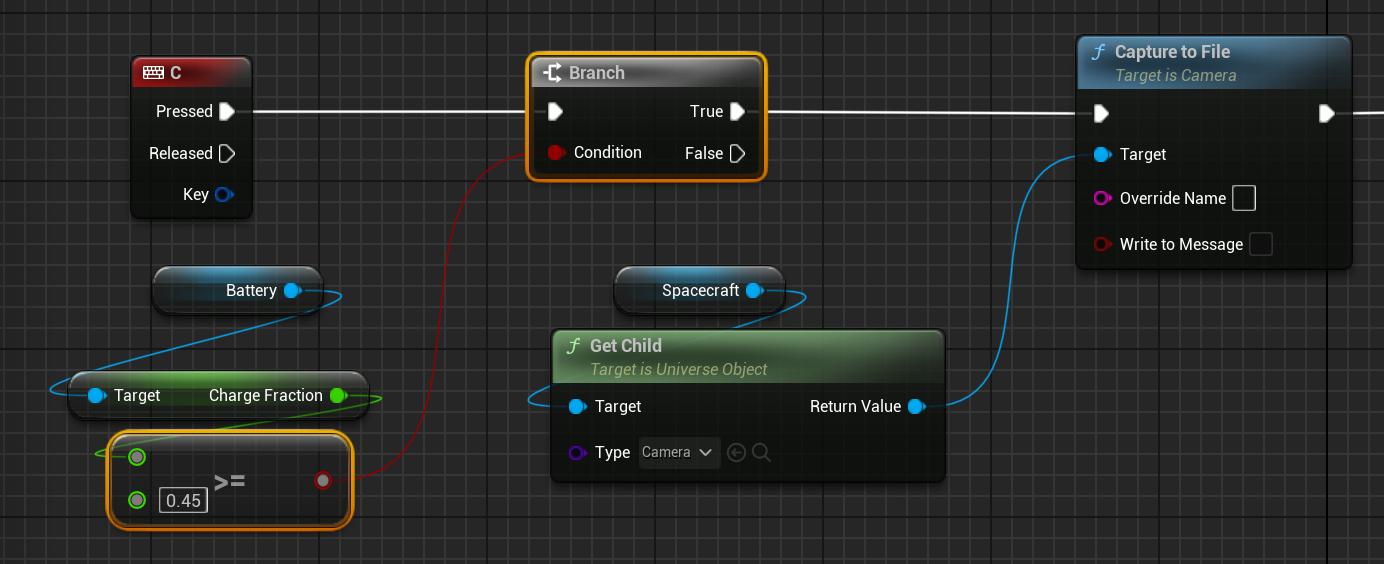
In this case, when the battery is low, it cannot take images until it charges above the 40% mark again.
Capturing Images
When the simulation starts, continuously pressing the capture button will allow the battery to decrease its storage to under 45%. When this happens, images can no longer be captured until the solar panels charge the battery back to their original level.