Camera payloads in Zendir Studio allow for the simulation of Optical, Infrared, and Event Camera types. Each camera has several properties that can be configured to emulate realistic camera imagery. This guide will focus on how to include and configure a Camera on a simulated satellite. The Camera document provides a greater explanation of the technical aspects and general use cases for each camera type. More information can be found there.
Camera Properties
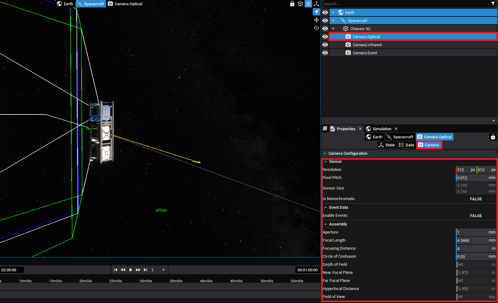
Within the Properties Panel of any of the Camera types, the following settings are available for the sensor and assembly:
Is Monochromatic: Switches the Camera from capturing Red, Green, and Blue (RGB) data to shades of grey (Monochromatic).Enable Events: Switches the Camera to only capture Event Data, which when enabled adds additional Camera Properties that can be configured.Resolution: The number of pixels in the sensor of a camera in the vertical and horizontal axes.Pixel Pitch: The distance in millimetres from the centre of a pixel and the centre of its neighboring pixels.Sensor Size: A non-configurable parameter that is calculated from the Resolution and Pixel Pitch of the camera.Aperture: The diameter of the opening of the lens in millimetres. A larger diameter/opening means a wider FOV.Focal Length: The Distance from the lens’s nodal point (where light converges) to the sensor in millimetres. A longer distance reduces the FOV.Focusing Distance: Defines the distance from the lens to where objects are in focus in meters.Circle Of Confusion: Defines the acceptable level of blur in millimetres, as measured on the sensor.Depth of Field: A non-configurable parameter that represents the distance where objects appear acceptably sharp.Near and Far Focal Planes: Related to the Depth of Field, these non-configurable planes represent the closest and furthest points where objects appear acceptably sharp.Hyperfocal Distance: A non-configurable distance between a camera and the closest object that appears in focus when the lens is set to infinity.Field of View: A non-configurable parameter that is the angle in degrees that represents the arc that the camera can see.
An example of these configurable and calculated parameters is below.
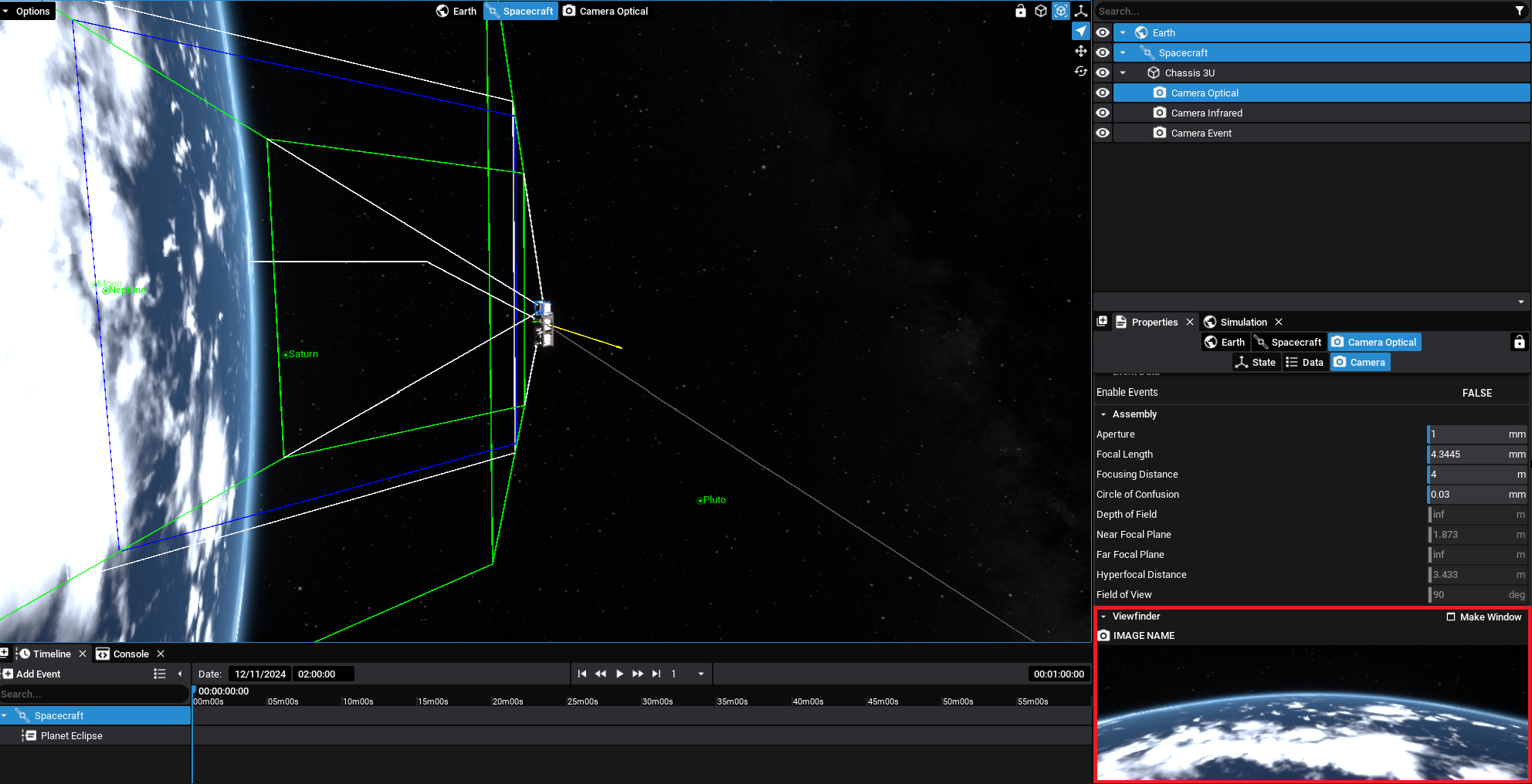
The Properties Panel also includes a live Viewfinder feed from the camera payload and the ability to export an image render to disk. The above optical camera properties result in the below Viewfinder image. Capture events have been configured for each of the camera payloads provided in the Inventory to generate an image mid-simulation.
NOTE
When the Camera is selected in the Properties Panel, the Field of View, Depth of Field Planes and Hyperfocal Planes are drawn to the screen.
Saving Images
Both during the simulation and when configuring the simulation, the Viewfinder window can be used to export images from the camera to disk and save them into a directory. The folder structure can be specified in the Directory field, with the Name field configuring the File Name.
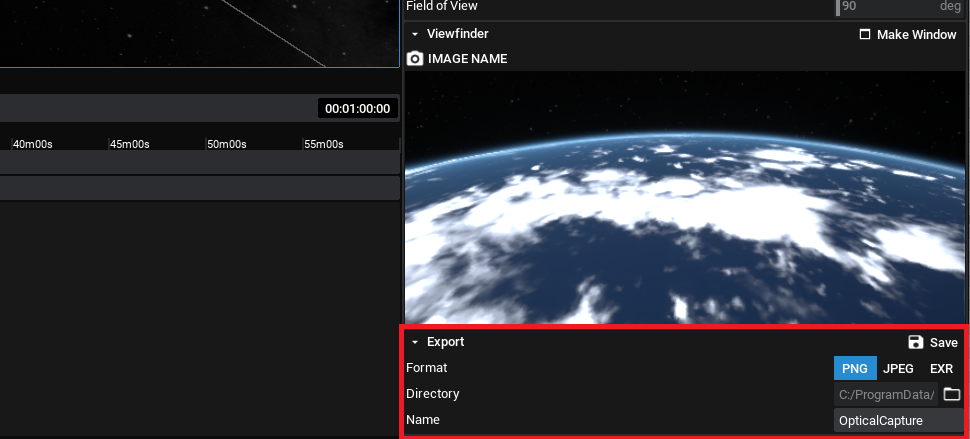
Selecting Save will save the image as it is seen then, with the appropriate camera settings, to the directory provided in the format of the camera. This will, by default, be a PNG. Both JPG and EXR options are available and can be configured on the camera properties.
Pop-Out Window
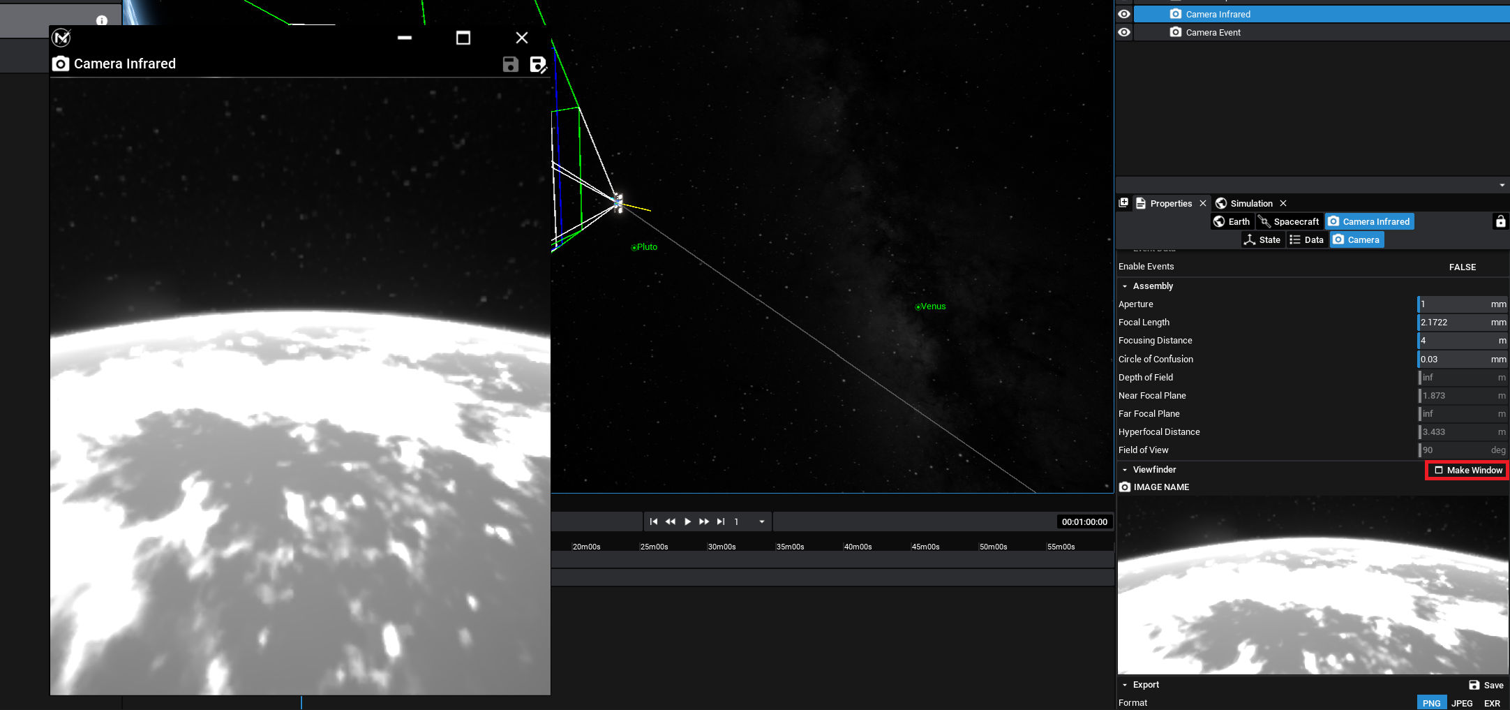
Additional to the Viewfinder is a camera widget that can be popped out of the screen. Selecting the Camera and then under the Camera view in the properties panel, there is an action to Make Window. This will create a new window that can be moved to another location on the Desktop, displaying the view of the camera outside of the panel. It can also be resized and scaled as appropriate.
NOTE
Additionally, clicking on the image in the panel will make a new pop-out window that will display the live camera feed. This can be resized and expanded.
Provided that the simulation is running, the Capture Image function can also be called via an action, both from an external action or manually, which will save the state of the image to the saved directory. This functionality works with all types of camera payloads.
Infra-Red Camera
The infra-red camera, also known as the heatmap camera, can provide a simulated image of the surrounding objects with a filter applied. The filter will change areas of the image based on the temperature or property of the object. By default, the camera will display the temperature of objects shown in the image, which may include other spacecraft temperature readings.
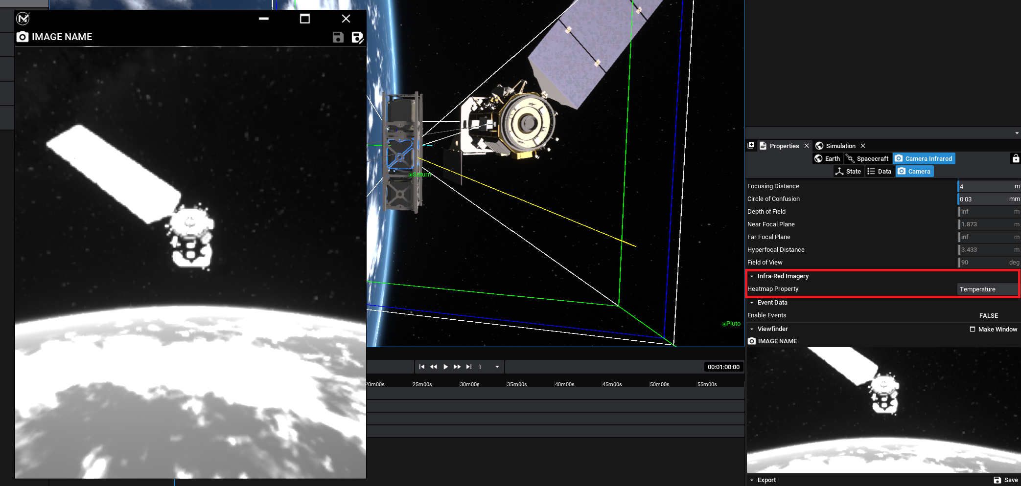
However, changing the Heatmap Property value will result in changing what that particular lookup will be. As an example, to show a heatmap of the mass of another spacecraft, the Mass property could be set instead. This may create a non-realistic image but can be used for certain simulations as demonstrations of how the property distribution of a spacecraft changes over time.
Event Camera
An event camera, also known as a neuromorphic camera, is an event-based camera that detects the difference in pixels, rather than the raw output from a lens. It contains a simulated processor that will compare the light data from each frame and determine the difference in values at each pixel. If the pixel delta exceeds a threshold, then a pixel event will be triggered. As a result, this produces data that are smaller in size and are useful for object detection algorithms.
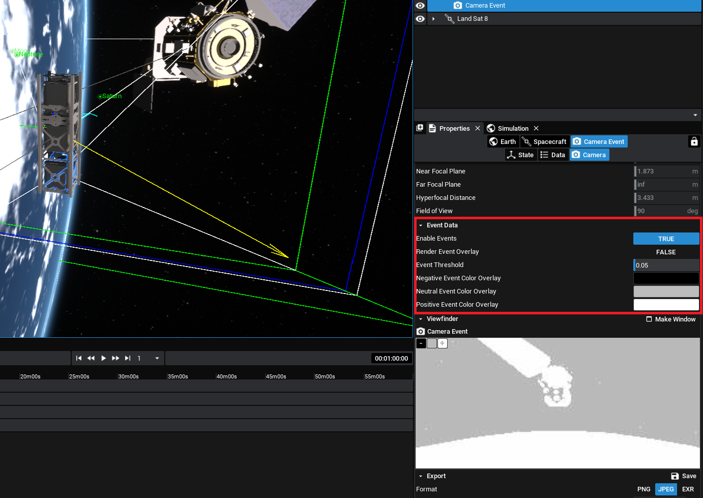
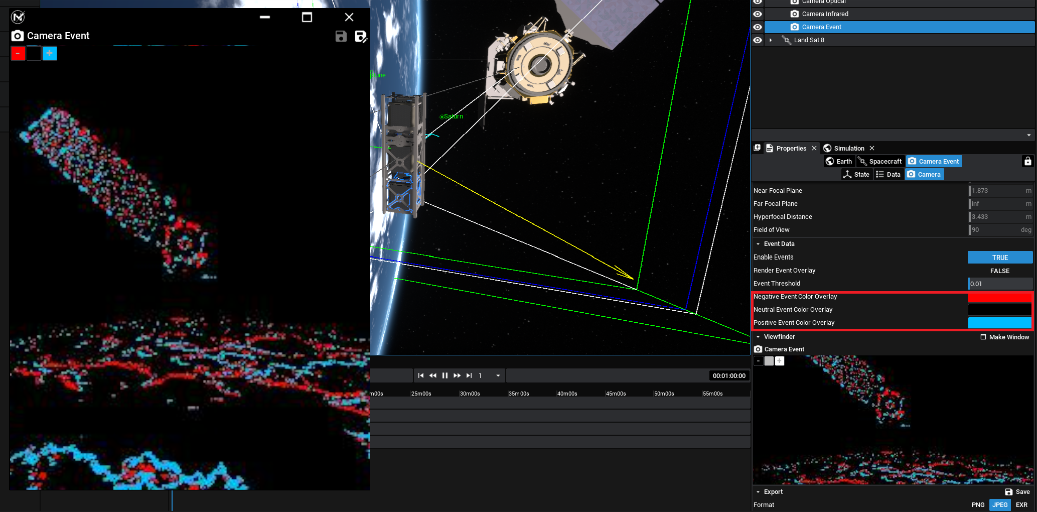
Both the optical and the infra-red cameras can be configured to be event-based by enabling the Enable Events option on the event camera. The threshold pixel value (between 0 and 1) can be set with the Event Threshold parameter. Additionally, the positive, negative and neutral colours of the event camera output can be changed for easier display.
NOTE
The event camera will only start comparing different event data when the simulation is running. Make sure to play a simulation before fetching data from the event camera.