Description
The power bus is the network manager that can manipulate and calculate the power usages on any entity. Components, such as Power Source, sinks, nodes and Battery, can be added to the power bus by connecting wires between them. As the simulation ticks, the power bus correctly computes the current, voltage and power draws from each of the components using the advanced circuitry simulation system. Components can be connected in series and parallel designs and any component terminal that does not have a wire connected to it is automatically connected to ground at the start of the simulation. This makes circuitry designs simple, yet allowing for complex designs for more advanced users.
Example Use Cases
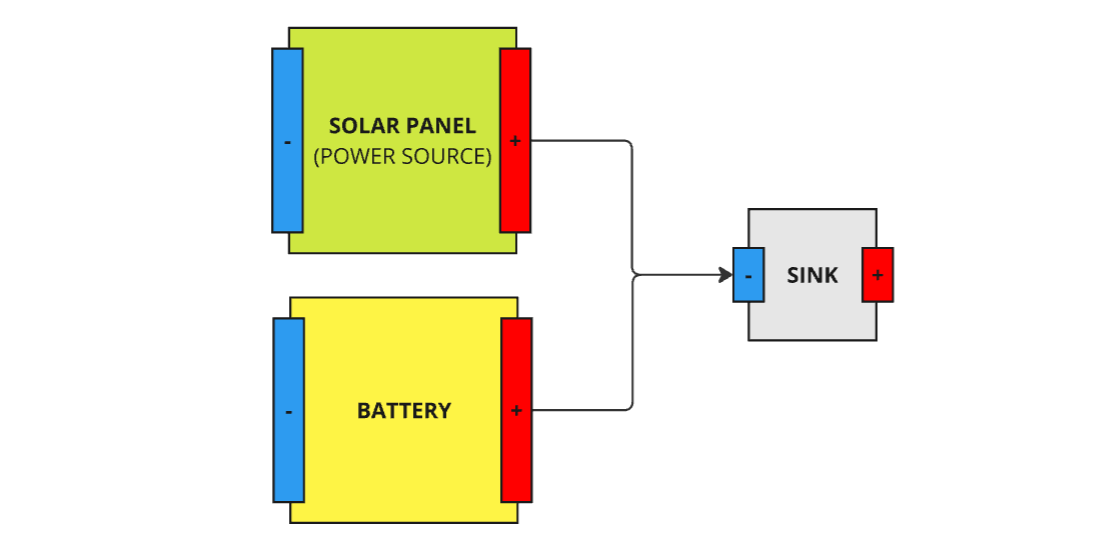
- Battery Charging: Connects a battery to a Solar Panel for simple battery charging from a power source.
- Complex Circuitry: Can be designed with parallel and series circuits in mind, with lots of components and branches from the battery.
- Power Analysis: Allows for current limiting and power management to return the total power draw from all components on the spacecraft’s circuitry.
Module Implementation
The power bus can be added to any entity and any component that exists on the entity can be connected to the network. The networked components are not automatically configured by default and must be configured using the connect functions. This will add virtual wires to the network by joining the components together. Each component, regardless of type (battery, source, model, sink, component), will have an input negative terminal and an output positive terminal. Conventionally, the circuit moves left to right, from negative to positive. However, the terminal connections can be adjusted.
To connect two components on the power bus network together, the Connect function is used. This will by default connect the positive terminal of the ‘from’ component to the negative terminal of the ‘to’ component. There is a more advanced function that can be used to connect other terminals of components together instead, if required. This is the Connect Terminals function and internally acts the same way. When connected, a wire is added from the terminals, which contains the information about which terminals and components are connected. Wires act as near-perfect conductors and contain an internal resistance of 1 pΩ.
Circuits
This circuit is a basic circuit for having a solar panel charge a battery whilst also discharging power to a sink.
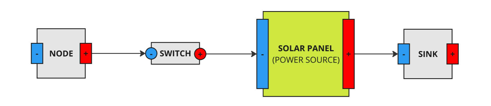
The following circuit shows a solar panel connected with a switch, a node and a sink. If the switch is open, then the network will not have a current. Otherwise, the solar panel can power the node and dissipate the rest of the power over the sink.
Corrections
The power bus can perform some corrections on the differences in power through the network. The Disable Excess Power Correction flag, which is true by default, is a flag that instructs the network to disable corrections to its simulation if power sources are over supplying power sinks. This means that the node models for power sinks will be calculated as if they were receiving the correct amount of power. This occurs when the total power generated is greater than the total power consumed on a single iteration of the network simulation.
The Disable Insufficient Power Correction flag, which is true by default, is a flag that instructs the power bus to disable corrections to its simulation if power sources aren’t meeting the expectations of power sinks. This means that the power node model data for power sinks will be calculated as if they were receiving the correct amount of power. This occurs when the total power generated is less than the total power consumed on a single iteration of the network simulation.
Assumptions/Limitations
The power bus is a complex model that enables advanced power functionality. However, it is restricted to some technical limitations for performance reasons. These restrictions are the following:
- Power components that exist on an entity will not be automatically connected (except in the case of Zendir Studio). Users are required to connect the components on the network together using wires between them.
- Power components cannot exits on two different networks. Connecting a power component that exists on a different network will result in it being removed from its previous network.
- Power components cannot be connected to itself. A wire cannot be used to connect one terminal of a component to the other terminal of the same component.
- Any terminal on a networked component that does not contain a wire will be connected to the ground plane. The functionality of the ground terminal is dependent on the power bus
Zero Ground Planeflag. - Components connected to the same power bus network must exists on the same root object as both the power bus and each other. Components that exist on different root entities will not be connected.
- Wires contain tiny non-zero resistance values, as a resistance of zero is not possible. These tiny values do cause tiny voltage drops in the rest of the network, but are small enough to be negligible in most cases.
- If a component connected to the network does not have a valid
Power Node Modeland is not a power component, then it cannot be added to the network.