By default, reaction wheels will not have power usage. An EPS (Electrical Power System) bus must be configured with a lookup table for a reaction wheel array to be connected properly. This guide will explain how to connect up the reaction wheels with the power bus for accurate power usage models and flight software connection. This tutorial assumes knowledge from the Reaction Wheel Power Software guide and an example of this software functioning must be done before attempting the steps shown here.
Configuring the Power Bus
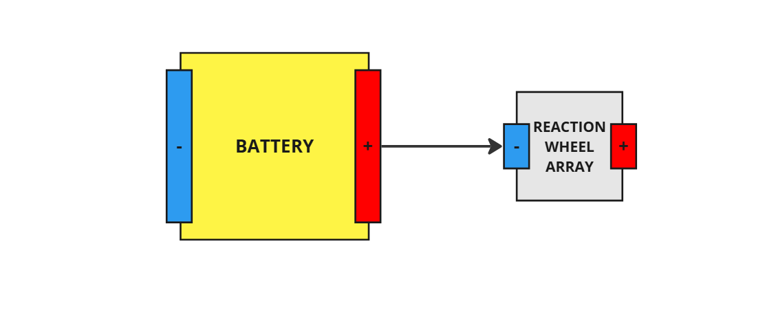
For this system to work, a Power Bus must be connected with a source of power for the reaction wheels. In this simple example a battery and a reaction wheel set is connected in series. This circuit is a basic example as additional switches, loads and sources can be added to the circuitry if required - this will not be covered by this tutorial however.
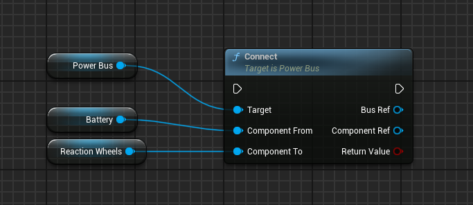
In Blueprints, this can be done using the Connect (Storage -> Node) function, which will attach a battery and a reaction wheel, connecting them in series.
NOTE
Other power components, such as current limiters, switches or loads, can be connected in series both before and after the connection between the battery and the reaction wheels. As long as the reaction wheels are connected in series to an energy source, then this process will work correctly.
Adding the Power Node Models
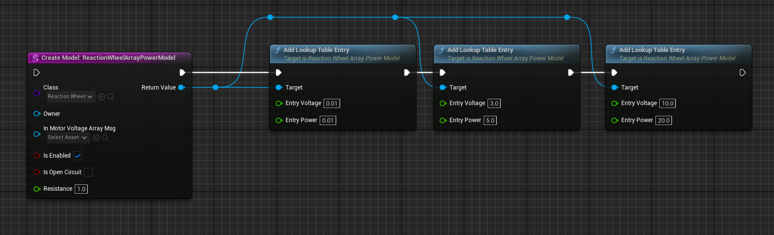
A Reaction Wheel Array Power Model is a model that enables the reaction wheel array to draw power from the power bus based on the array voltage messages that are created by the flight software. This can be added using the Create Model node and selecting Reaction Wheel Array Power in the class dropdown. The reaction wheels are the target of the model.
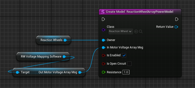
The In_ArrayMotorVoltageMsg specifies the voltage input from the reaction wheels, calculated by the flight software defined later on this guide. This can either be connected on the constructed or later. In this case, the value is set when creating the Model. However, before creating the Reaction Wheel Array Power model, an instance of the Reaction Wheel Mapping software is required.
This comes from the RW Voltage Mapping Software software node and is named Out Motor Voltage Array Msg. Setting the input message of the power model will connect the messages correctly, as shown above.
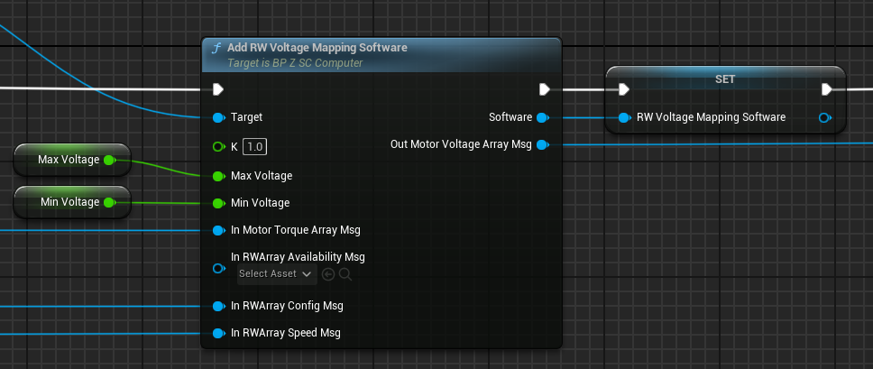
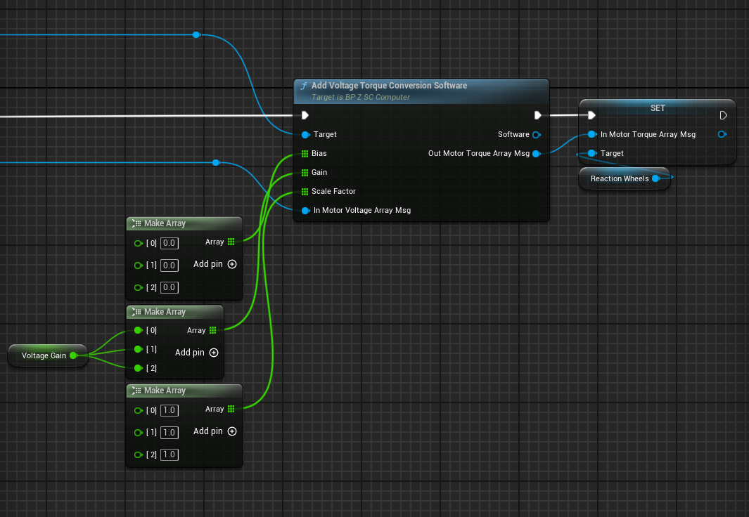
The same output Out Motor Voltage Array Msg from the software can then be connected to the Motor Voltage Torque Conversion software when constructing the previous software node. The output Motor Torque Array Message is then connected to the matching input message on the Reaction Wheels.
NOTE
Both the input and output messages for the power model are of the same type. The message outputted will be zeroed if the power bus has no more power and will ensure that the reaction wheels do not move if this occurs. Additionally, if a voltage or current limit is applied to the power network, then the final voltages and current will be scaled down appropriately to meet this cap.
Adding Lookup Tables
By default, the motor power model will not be able to associate any voltage with power. A lookup table is required to be loaded to convert voltage inputs into power draws. The Add Lookup Table Entry allows for multiple lookup tables, in the form of Motor Voltage LUT, to be added to the power model. These correlate voltage to power levels and a linear curve is created between the points provided when calculating the power based on a voltage sum that is in between two points. It is important to note that the curve data from the last two points extends past the last point when calculating the power draw for large voltages.
NOTE
Ensure that for each entry added, the voltage increases in value.
Demo Result
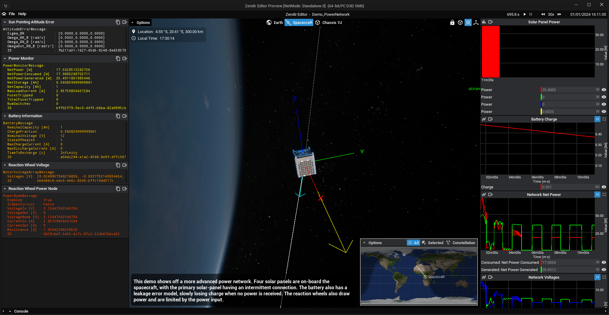
When running the Power/Demo_PowerNetwork demo, which demonstrates the reaction wheel power software and EPS bus, when the spacecraft reaches the expected target attitude, the voltage polarity will alternate fur to the main solar panel’s Unsteady Error Model applied.