Description
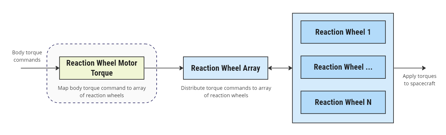
As illustrated in the below figure, the purpose of this module is to map a desired torque command in the body frame to an array of Reaction Wheels. In the case that one or more reaction wheels are specified unavailable (e.g. the user has specified them as broken), the module will attempt to generate a solution without these wheels. The user must specify a reaction wheel configuration to the module, in particular the steering matrix , which is a matrix composed of the spin axes of each reaction wheel i.e. it provides the map of vectors about which each reaction wheel can generate torque. The user must also specify the target control axes. The module will then attempt to compute the torque array that maps the desired torque commands to individual reaction wheels.
Example Use Cases
- Map command torque to RW Array: The primary purpose of this module is to map command torque to an array for reaction wheels.
- Model flight software misconfiguration errors: Misconfigurations of flight software knowledge of the actual dynamic configuration of systems is a common error. This can be simulated by providing an invalid steering matrix and/or control frame configuration.
Module Implementation
Given the steering matrix , the map between and is simply,
However, the user may define a separate control frame , that may indicate reduced degrees of freedom e.g. no command torques may be applied about the body frame’s z axis. In this example, the user would then specify the DCM as,
This would then require the desired torque and resulting command to be mapped to as follows,
The torque array can then be solved for using a minimum norm solution [1], such that,
Assumptions/Limitations
- If no valid solution for is found, then the output torque command is a zero vector.
References
[1] Hanspeter Schaub and John L. Junkins. Analytical Mechanics of Space Systems. AIAA Education Series, Reston, VA, 3rd edition, 2014.