Description
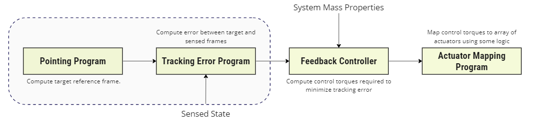
The purpose of this module is to provide a sun “safe” pointing mode i.e. given an input sun direction and estimated (or actual) body frame , this module aims to drive a body-fixed Spacecraft vector to . This can be used to drive a solar panel to align with the sun. If the sun vector provided is invalid, a fallback pointing mode is applied, in this case, a tumble. A tumble mode may not be considered a safe alternative in all missions. As shown in the figure below, it covers both the pointing program and tracking error program in an ADCS software chain, as the switch’s pointing program and error tracking are based on the sensed states.
The module also accepts an inertial body angular velocity vector as an optional input. Given that the desired sun-pointing orientation is inertial, the inertial frame acceleration is set to zero, while the reference rate is either zero or the desired sun-heading roll vector.
NOTE
This module does not establish a unique sun-pointing reference frame as the pointing condition is an under-determined 2 degree of freedom condition. For sun pointing applications this is practical as the power generation does not (typically) depend on the orientation about .
Example Use Cases
- Provide a sun-pointing model to an ADCS controller: This module is designed to work at the end of an attitude guidance chain, where it feeds a guidance error (delta between desired and sensed) state, into the controller.
- Pointing a Solar Panel: Can aim a solar panel towards the sun for optimal charging.
Module Implementation
The module implementation considers three cases:
Case 1: Good Sun Pointing Vector
The principle rotation vector of is:
NOTE
The vector does not have to be normalized as an input vector.
The principle rotation angle between and is then simply:
The rotation from to written as a set of MRPs is then:
Where is the attitude error output of the guidance message. If a nominal spin rate about the sun heading axis is specified, then:
If the spacecraft is to be brought to rest, then should be set to zero. Otherwise, the tracking error angular velocity is computed as:
Finally, the assumption is made that the roll about the sun heading has a constant magnitude and inertial heading such that .
Case 2: No Sun Vector:
If is less than the module parameter MinUnitMag, then it is assumed that there is no good sun heading and the attitude tracking error is set to zero.
Further, if there is no good sun heading, the module allows for a non-zero body rate to be added. This allows the spacecraft to establish a constant rate tumble specified by such that:
This is to provide safe behaviour in the event that the lack of a sun measurement is not due to eclipse but due to a sensor failure. In the case of a sensor failure, a constant tumble will produce, on average, some level of power as the solar panels will eventually face some level of sunlight.
Case 3: Ill-defined Sun Vector
For the case where , is not well defined. To catch this error, let be a pre-determined small angle. Then, if set the attitude tracking error to:
However, if then we must determine an orthogonal eigen-axis to must still be determined. Considering the body frame , we may determine an eigen-axis as:
If , then will be ill-determined. In this case,
As cannot align with both and , this approach determines a unique rotation that is close to 180 degrees () for this special case.