Description
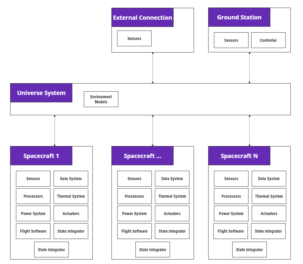
The spacecraft module is a special implementation of the core DynamicBody class, which is an abstract class that handles the modular integration of 6 degrees of freedom (6dof) equations of motion using a back substitution method. The spacecraft module is designed to act as a container and manager for Components, which includes both physical and virtual (software) components. When created, it will automatically search for and connect to an available Universe system, which provides the default communications bus between the spacecraft and other modules as illustrated in the diagram below.
NOTE
The spacecraft and other modules can publish/subscribe to messages generated by other modules directly without using the Universe as the common data bus but this would impact the ability of other modules to access this data. The advantages/disadvantages of this are very case-dependent.
The following description of the module implementation provides a general breakdown of core spacecraft behaviors. The provided pseudo-code is simplified for clarity of explanation. It does not include additional optimizations or error catches and is used solely for the purpose of explaining the systems.
Example Use Cases
- Any Satellite Simulation: The spacecraft object provides the baseline container for modelling spacecraft dynamics. Special instances that use lookup tables or only propagate 3 degrees of freedom orbits are discussed elsewhere.
Module Implementation
OnBegin
At the beginning of every simulation, the spacecraft will run the following procedure:
-
Create a new integrator
Initializes the local integrator that the spacecraft will use to propagate
StatePropertiesandVectorProperties. This integrator is specified by the user which is theRK4integrator by default. Components may initialize their own internal integrators (e.g. a local Euler model) or connect to the spacecraft integrator. To connect to the spacecraft integrator, they must use theRegister Statesoverride on the component class. Below is a simplified example from the reaction wheel array module:
public override void RegisterStates(StateProperties properties)
{
  base.RegisterStates(properties);

  // Loop through an array of RWs and set container object

  // Create the RW wheel state integrator
  OmegasState = properties.Get("reactionWheelOmegas", (uint)NumRW);
  ThetasState = properties.Get("reactionWheelThetas", (uint)NumRW);

  // Set the inital values
  OmegasState.SetValue(omegasForInit);
  ThetasState.SetValue(thetasForInit);
}-
Ensure this body is attached to the Universe Checks to make sure that the spacecraft has been attached to the Universe. If not, it creates a new attachment.
-
Create the Gravity Effector class Initializes a
GravityEffectormodule and attaches it to the spacecraft. This is required because theDynamicBodydoes not, by default have to represent an orbiting object. The gravity effector component will evaluate gravitation contributions to the spacecraft’s EOMs. -
Attach the Body Effector class The
BodyEffectorclass is a general container for kinematic data (position, velocity, attitude, rotation). The Spacecraft / Dynamic Body does not store these by default. -
Initialise the Dynamics The final step to begin is to pre-initialize the dynamic information of the simulation prior to the first tick call. As shown in the below pseudo-code this is essential to ensure correct cross-initialization of all child components and pre-condition the simulation with correct state information prior to the first integration step. It also ensures that the spacecraft all components have correctly published output message data.
void InitialiseDynamics(double time)
{
  // Update the Component list of all objects attached

  // Initialise effectors components

  // Update the Mass Properties at the time

  // Update the position and velocity with respect to the centre of mass differences

  // Call the equations of motion at the initial time
  UpdateEquationsOfMotion(time, 0)

  // Compute Energy and Momentum at the initial time

  // Write output messages for spacecraft and all child components
}
OnUpdate
The DynamicBody’s OnUpdate function is relatively trivial:
- Triggers a domain-specific integration function.
- Triggers the parent object and all child components to update their messages.
NOTE
It’s important that the parent object triggers child components to write out their messages unless there is a specific reason to trigger this writing step early. This is to ensure that components do not provide out-of-sync data to dependent modules.
These can be further broken down as follows:
- This step triggers the integrator attached to the spacecraft, where registered variables are propagated forward. As a simple example, the below code block shows the Euler method’s integrator. It’s here that the equations of motion (EOM) of the object are integrated. The implementation of the spacecraft EOMs is described in the following section.
public override void Integrate (double prev_time, double step)
{
    // Perform an Euler update
    // dy/dt = f(t, y), y(t_0) = y_0
    // t_{i+1} = t_i + h
    // y_{i+1} = y_i + h*f(t_i, y_i)

    // Update the state using the current derivative

    // Update the derivatives at the new state
    Object.UpdateEquationsOfMotion(prev_time + step, step);
}- By default, the spacecraft does not own any mass properties. If an
OverrideMassPropertiesflag is set on the spacecraft, this function will be skipped. This means that mass properties will remain fixed and theUpdateMassPropertiesfunction on components will not be updated. While this will be more performant, it may cause undesired behavior in state effector modules where their contributions to system mass properties cause internal forces/torques e.g. fuel burn models. Total system mass property calculations are discussed further in the following section.
void UpdateMassProperties(double time, double step)
{
    // 2.1 - Get all components and call update mass properties
    foreach (var component in ChildComponents)
    {
        // Call mass properties on the physical object
        component.UpdateMassProperties(time, step);
    }

    // 2.2 - Updates the output messages from the totals calculated
}- By default, the spacecraft also computes other parameters of interest, specifically accumulated , non-conservative accelerations, and total system energy and momentum. These are useful parameters to support mission analysis and verify simulation behavior e.g. if a method is supposed to be energy/momentum conservation, comparing initial and final energy states is important. Not all modules are energy and/or momentum conserving e.g. Reaction Wheel simple jitter does not conserve momentum, but the fully coupled jitter model does.
UpdateEquationsOfMotion
To integrate the contribution of spacecraft components into the total system dynamics in a modular way, the spacecraft uses the back substitution method described here [1], where the goal is to structure the equations of motion (EOM) of the spacecraft and the contribution of components into the following matrix form,
This allows the modular contribution of components to the total system dynamics to be super-imposed through their contributions to , , , , , , without a priori knowledge on the form of these contributions. This system of equations can then be solved as follows [1]:
With that goal in mind, the EOMs of the spacecraft can be written as [1],
where:
- is the total mass of the spacecraft.
- is a 3x3 identity matrix.
- is the spacecraft’s total moment of inertia in the body frame in the body frame .
- is the rate of change spacecraft’s total moment of inertia in the body frame .
- is the acceleration of the spacecraft body frame with with respect to the inertial frame .
- is the vector that describes the distance between the body frame and the spacecraft’s total center of mass.
- is the rate of change of the total spacecraft center of mass in the body frame .
- is the angular velocity of the spacecraft body frame with respect to the inertial frame .
- is the attitude of the spacecraft body frame with respect to the inertial frame .
- are external forces being applied to the body in the body frame .
- are external torques being applied to the body in the body frame .
Note: is the matrix representation of a cross-product operation.
As indicated in the below pseudo-code, this is the approach taken here:
void UpdateEquationsOfMotion(double time, double step)
{
    // 1 - Update the Mass Props at the time
    UpdateMassProperties(time, step)

    // 2 - Compute the kinematic properties relative to the
    //     total system mass properties

    // 3 - Compute the Gravity at this location

    // 4 - Loop through effectors and collect their contributions to
    // the back substitution matrix and external forces/torques
    foreach (var component in ChildComponents)
    {
        // Get all physical components to report their contributions to the EOMs
        component.UpdateContributions(time, step);
    }

    // 4 - Compute the Derivatives of the Body
}
NOTE
It is important that the
UpdateMassPropertiesfunction is called both here and atOnUpdate. The firstOnUpdatecall makes sure that theUpdateMassPropertiesfunction has been correctly called prior to integration. It’s called here is essential to provide correct mass properties information from components at intermediate turns during integration steps. If this is not done correctly, it may result in numerical errors.
- As in the OnUpdate step, the mass properties of the spacecraft components are updated.
- The EOMs propagate the inertial state of the body frame . The reason that the frame is used is that the total system mass properties are not assumed to be known by the child components at the point that their contributions are calculated. Nevertheless, forces and torques must strictly be applied relative to total system mass properties. To compute the total system mass properties, all components track both their orientation relative to the body frame along with their mass properties in their local component frame . The spacecraft may then request total mass property information, which triggers a recursive call through child component hierarchies to compute each component’s contributions to the total system mass properties, specifically the total system mass, the total center of mass and the total moment of inertia about the center of mass and their corresponding rates, all in the frame. A more detailed breakdown of the mass system is covered in a dedicated technical note.
As discussed in the OnBegin function, the spacecraft attaches a gravity effector module. A specific call is made here to compute the gravity contribution given and .
- This step loops through all child components and collects their contributions to the EOMs as defined in the back substitution method above.
- Completes the back substitution method by solving for and as defined above.
Assumptions/Limitations
- By default, the spacecraft object does not have its own mass properties - all mass properties should be calculated from attached physical components. The exception to this is if the override mass properties flag is set to true, in which case the mass properties of the spacecraft must be set by the user.
- Limitations and assumptions are primarily inherited from attached components.
- Simulation accuracy is strongly linked to integrator and integrator step size. It’s up to the user to ensure that numerical errors due to selection or integrators and step size are minimized as this is a function of specific use cases.
References
[1] Hanspeter Schaub and John L. Junkins. Analytical Mechanics of Space Systems. AIAA Education Series, Reston, VA, 3rd edition, 2014.